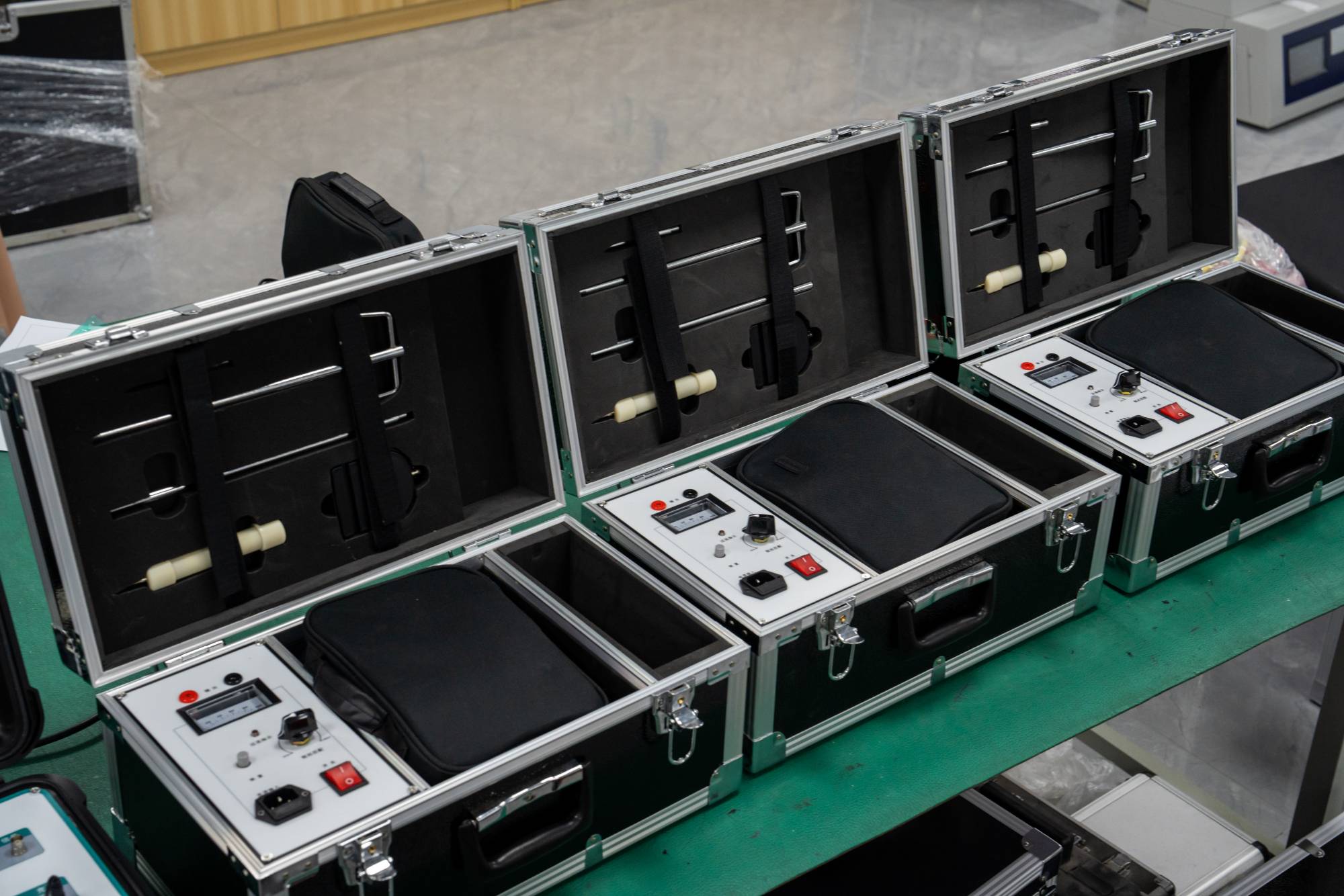
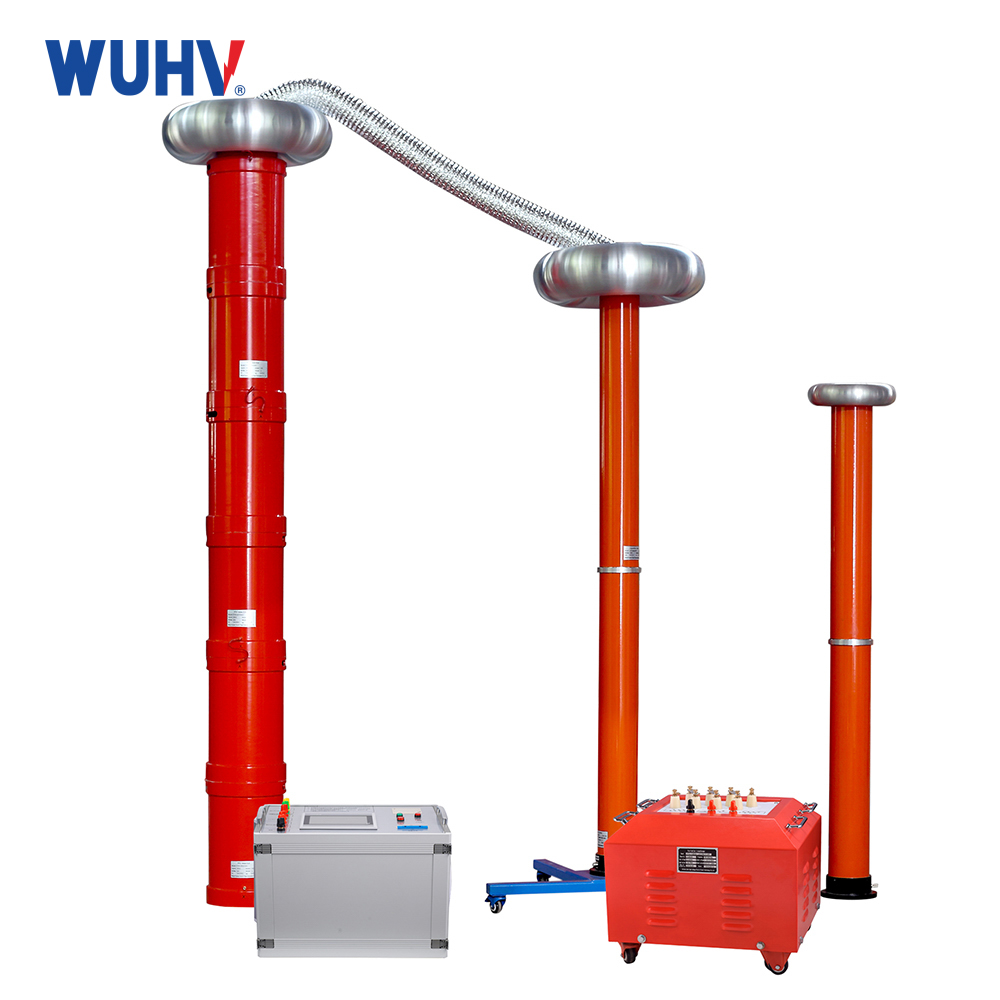
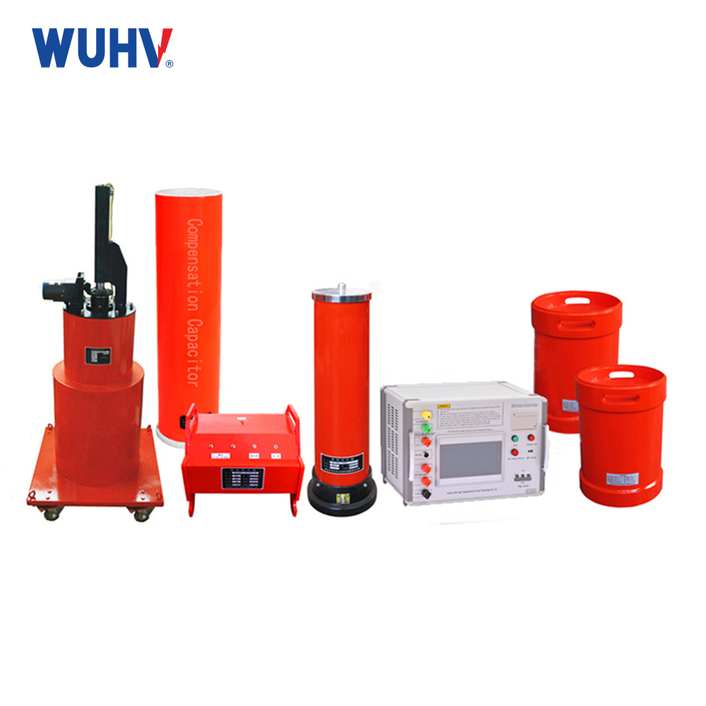
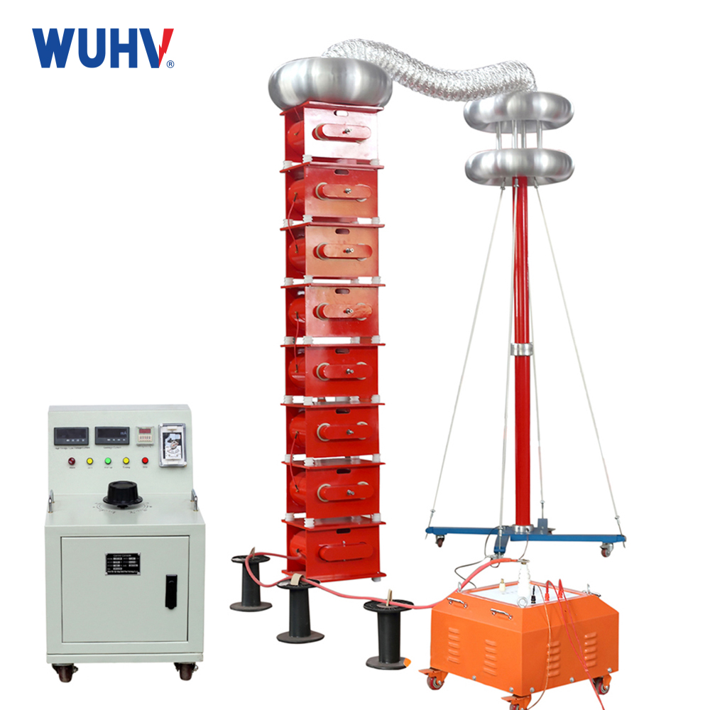
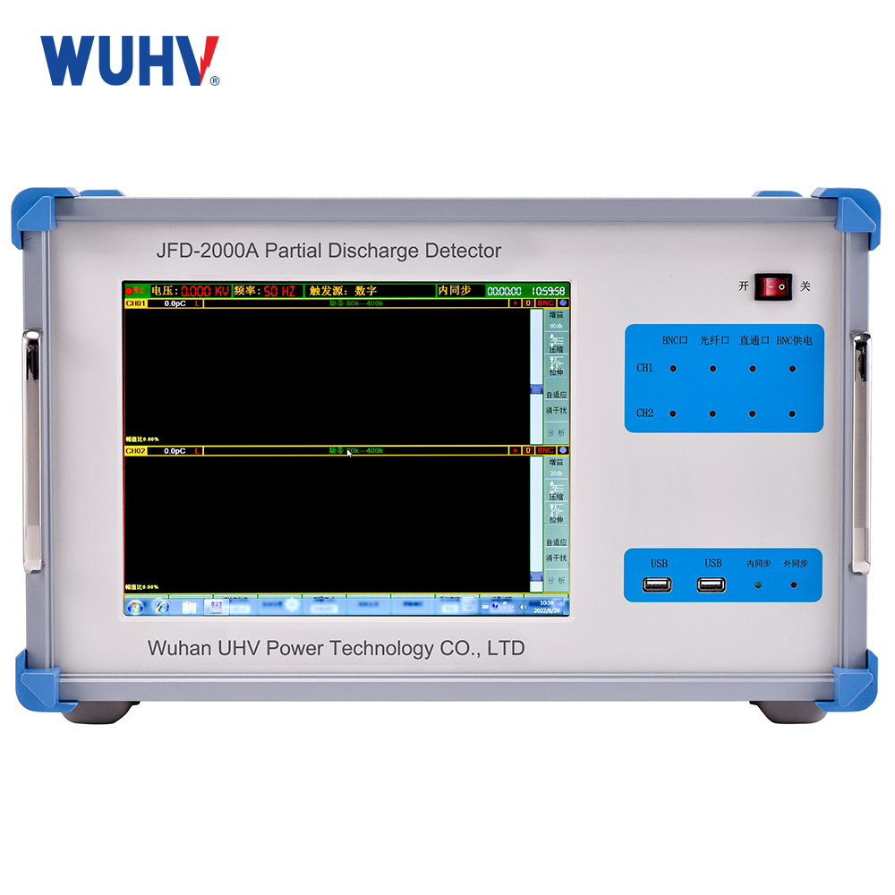
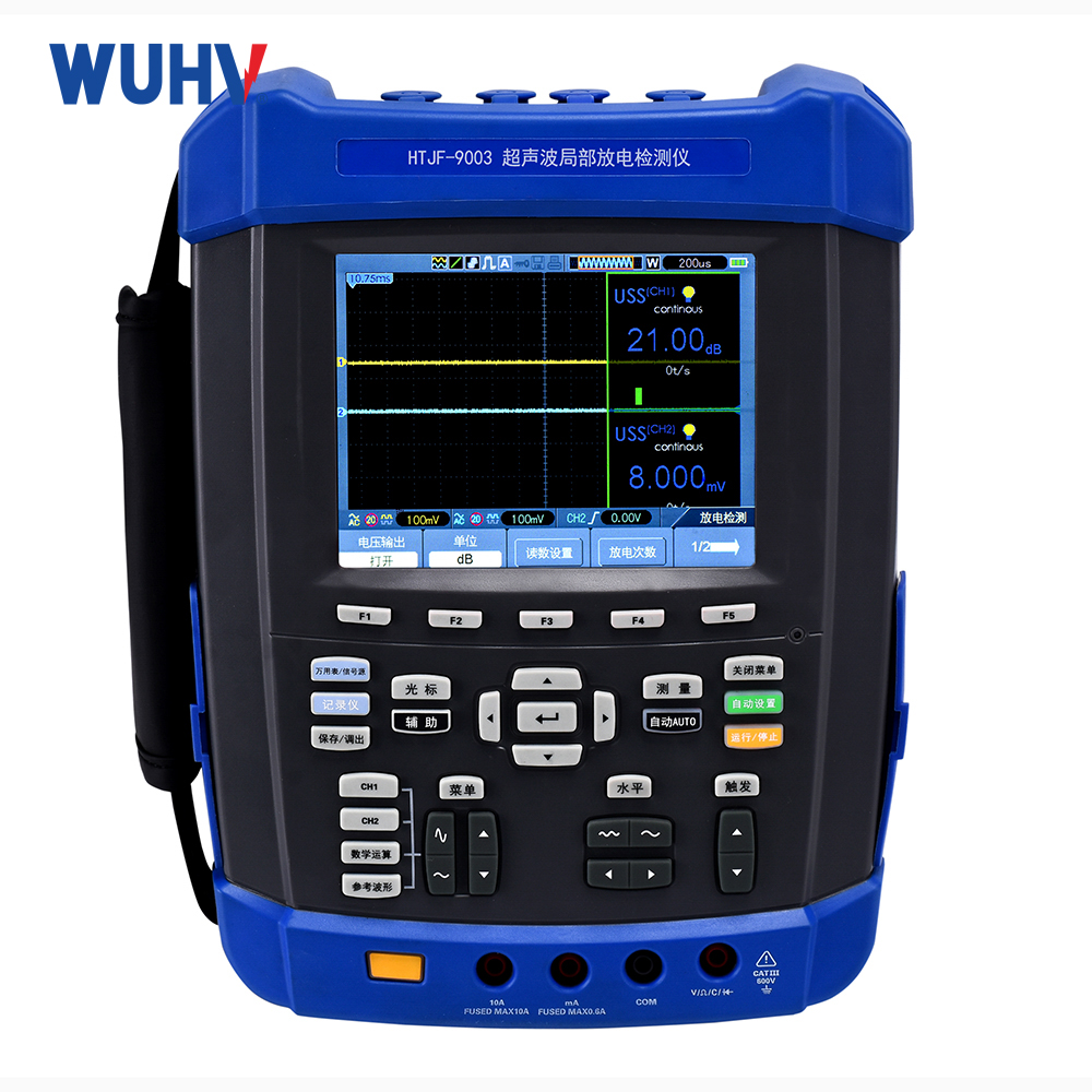
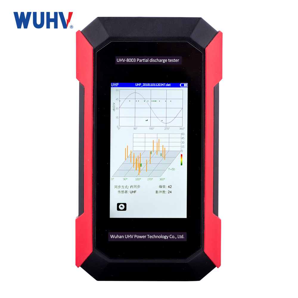
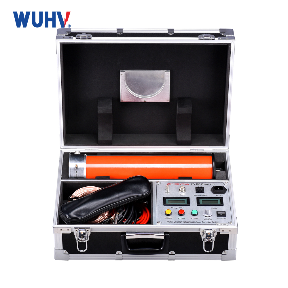
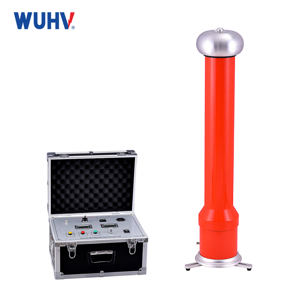
Thecable fault testerunder UHV power can help many power workers conduct various power tests more conveniently.
1. Fault diagnosis:
The nature of cable faults can be simply divided into the following categories:
1) Breakage: One or more core wires of a cable are disconnected, causing a signal interruption. This type of fault is detected using the pulse method.
2) Mixed wire: There are three types: grounding, self mixing, and other mixed wires, which refer to insulation layer damage between core wires and leads, between the same pair of core wires, and between core wires. The insulation resistance of different pairs of wires drops to a very low level (several hundred to several thousand ohms), and even short circuits, seriously affecting signal quality. This type of fault can be tested using the pulse method first, and when the waveform of the cable fault tester is difficult to recognize, the bridge method can be used for side measurement.
3) Poor insulation: The insulation material of the cable core is invaded by water or moisture, causing a decrease in insulation resistance, resulting in poor communication quality, and even blockage. This type of fault is similar to self mixing, mixing, and grounding, but the fault resistance is relatively high. (Over several thousand euros), the degree of malfunction is relatively mild. Generally, insulation resistance less than 2 megohms can affect signal quality and needs to be eliminated. This type of fault is generally not detected by pulse method and needs to be replaced by an electric bridge.
After a line fault occurs, tools such as measuring meters, megohmmeters, and multimeters should be used first to determine the nature and severity of the line fault, in order to select appropriate testing methods.
The tester understands the direction of the circuit and the fault situation, which helps to quickly determine the fault point. When a cable fails, it is necessary to comprehensively consider the time of the fault, the scope of the fault, the environment in which the cable line is located, the location of the joints and manholes, the influence of the weather system, and possible problems. Based on the measurement results, roughly determine the faulty section.
2. Select testing method:
When the fault resistance is less than a few hundred to several thousand ohms, we become a low resistance fault, otherwise it is called a poor insulation or high resistance fault. There is no clear boundary between high resistance and low resistance.
The pulse method is suitable for detecting broken and low impedance mixed line faults. Severe insulation faults can sometimes be detected using the pulse method. The pulse method is intuitive and easy to operate, without the need for peer cooperation. It should be used first during testing.
The bridging method can test for high resistance insulation faults, but it requires finding the wire and coordinating with the other end, and the preparation for testing is also quite complicated. After confirming that the pulse testing method cannot be detected, the bridge method should be used.
3. Fault location:
During testing, the local equipment connected to the faulty line pair should be disconnected first. First, conduct on-site testing to determine the minimum segment of the fault point, and then repeat the testing on site to determine the precise location of the fault point.
4. Fault location:
Based on the test results and drawings of the instrument, the specific location of the fault point was calibrated. When the drawing information is incomplete or incorrect, the approximate location of the fault point can be estimated based on the cable line situation that is known, and then the cause of the fault can be analyzed based on the fault situation and surrounding environment until the fault point is determined. For example, if there are connectors within the estimated range, the fault point can be roughly determined to be in the connector. The longer the measurement range, the greater the measurement error.


