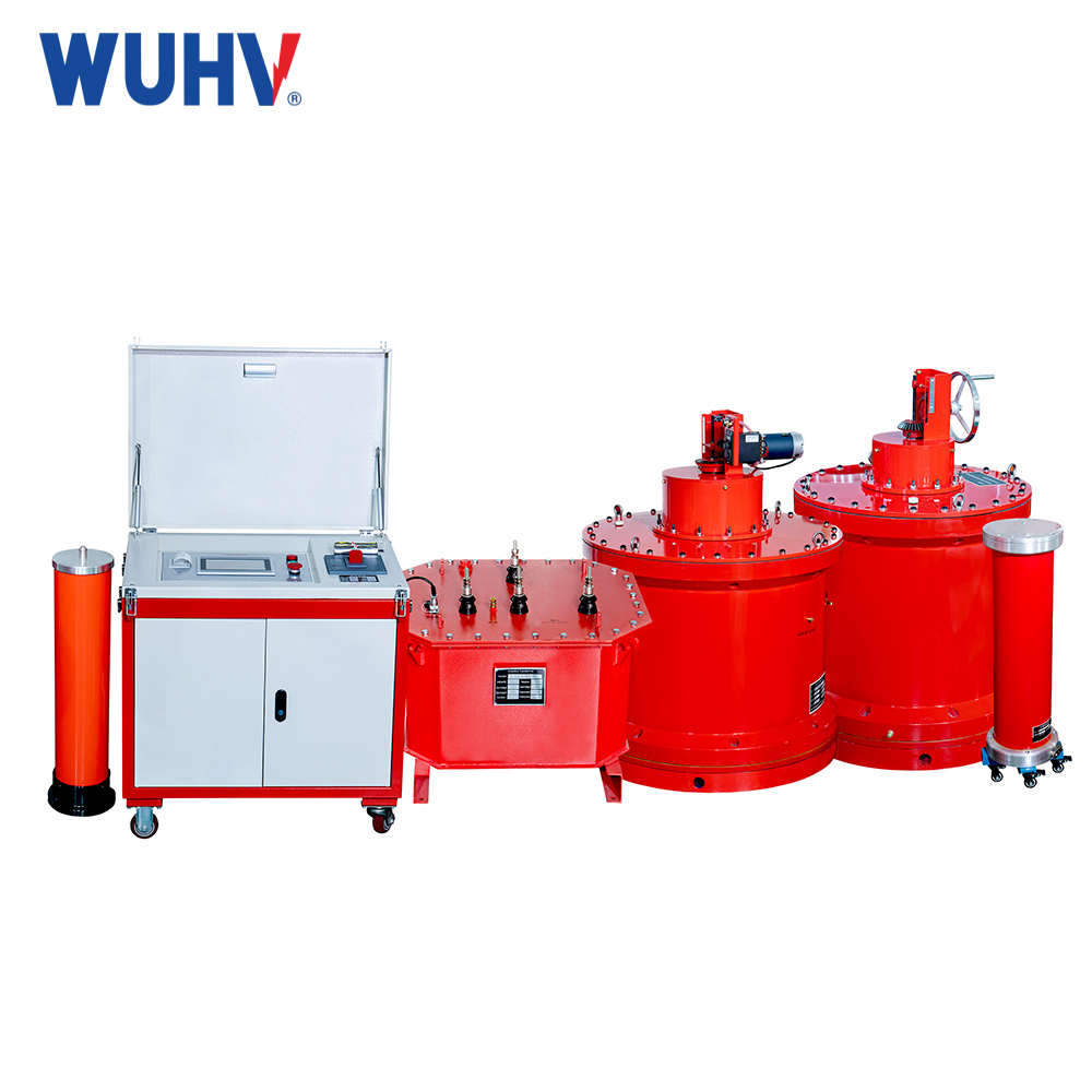
の直列共振 under Wuhan UHV can help many power workers conduct various power tests more conveniently.
In the high-voltage equipment family of the power system, cables GIS、 Generators and other components are the 'arteries' that ensure stable power supply. To ensure the reliable and safe operation of these "arteries" insulation, a precise and efficient "physical examination" technology - series resonance withstand voltage test is indispensable. Today, we will delve into the analysis of the series resonance test device and uncover the secret behind its efficient completion of high-voltage testing.
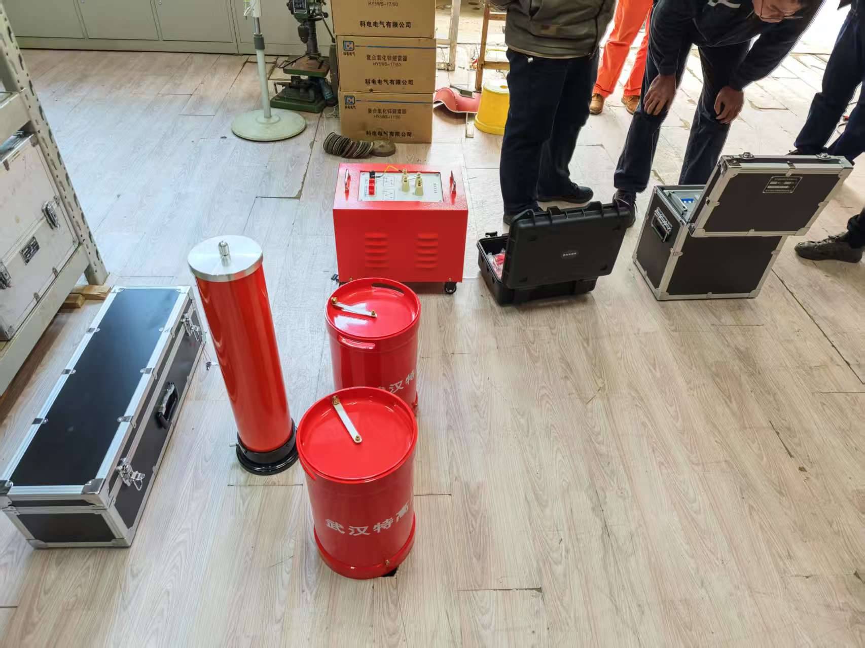
1、 What is series resonance withstand voltage test?
The series resonance withstand voltage test is a method of using the LC 直列共振 principle to test power cables, transformers GIS、 The core test for insulation performance testing of high-capacity capacitive equipment such as generators. When the inductance L of the reactor in the test circuit reaches resonance with the capacitance C of the test sample at a specific frequency, the circuit exhibits pure resistance characteristics. At this time, only a very small excitation power is required to generate a high test voltage far exceeding the input at both ends of the test sample.
2、 Key factors affecting the success or failure of experiments
To ensure the accuracy of the series resonance test, the following factors are crucial:
Parameter matching degree: The inductance of the reactor and the test frequency must be accurately matched with the capacitance of the tested object (resonance frequency f=1/(2 π√ LC)), otherwise resonance cannot be established or the voltage cannot rise.
Environmental conditions: The experiment should be conducted in a dry, ventilated, and non strong electromagnetic interference environment; Moisture, dust, and high temperature can reduce equipment insulation, affecting Q value (quality factor) and test stability.
Equipment accuracy: The accuracy of variable frequency power supply, voltage divider, and reactor directly determines the accuracy of voltage and current measurement, and excessive errors can lead to misjudgment.
Wiring and grounding: High voltage wiring should be firm and have sufficient insulation distance; Poor grounding can cause interference, protection misoperation, and even safety accidents.
3、 The 'core component' of a series resonant device
A complete series resonance test device consists of five key components:
1. Variable frequency control power supply: device "brain", output adjustable frequency of 30-300Hz, automatically track resonance point, with multiple protections for overvoltage, overcurrent, and flashover
2. Excitation transformer: "Step up bridge", which boosts the low-voltage signal of the variable frequency power supply and matches the working voltage of the reactor.
3. High voltage reactor: "resonant core", forms a resonant circuit with the tested capacitor, and adapts to different voltage levels through series/parallel combination
4. Capacitive voltage divider: "Accurate ruler", real-time measurement of high voltage side voltage, feedback to the control system, ensuring accurate and stable voltage
5. Compensation capacitor (optional): "Auxiliary partner", compensates for the capacitance of small capacity test samples, and expands the applicability of the device.
4、 Standard Test Operating Procedure (Simplified Version)
1. Preparation stage: Check the appearance of the equipment and ensure that the wiring is intact; Install safety fences and hang warning signs; Confirm the parameters of the test sample and calculate the matching reactor combination.
2. Wiring connection: Connect the wires in the order of "low voltage first, high voltage second, and finally grounding"; Maintain a sufficient safe distance from the high-voltage section.
3. No load tuning: Do not connect the test sample, start the device to automatically scan the frequency, confirm that the resonance point can be found stably, and verify that the equipment is normal.
4. Formal experiment: Connect the test sample and automatically/manually tune it; Slowly increase the voltage to the specified value and maintain the standard withstand time (such as 60 minutes for cables).
5. Monitoring records: Real time recording of voltage, current, frequency, and temperature; Observe whether there is any abnormal noise, smoke, or flashing phenomenon in the test sample.
6. Closing of voltage reduction: Automatic voltage reduction to zero at the end of the experiment; Open the circuit first and then disconnect the power supply; Fully discharge the test sample and remove the wiring.
5、 The 'Advanced Secret' to Make Experiments More Efficient
1. Intelligent selection: Based on the capacitance and test voltage of the test object (cable/GIS/generator), accurately match the series parallel connection mode of the reactor.
2. Regular calibration: Calibrate the variable frequency power supply and voltage divider annually to ensure accurate parameters and avoid data deviation.
3. State maintenance: Check the insulation of the reactor and voltage divider before and after the test; Clean the equipment in a timely manner to prevent moisture and dirt accumulation.
4. Formal experiment: Connect the test sample and automatically/manually tune it; Slowly increase the voltage to the specified value and maintain the standard withstand time (such as 60 minutes for cables).
5. Monitoring records: Real time recording of voltage, current, frequency, and temperature; Observe whether there is any abnormal noise, smoke, or flashing phenomenon in the test sample.
6. Preferred brand: Choose professional manufacturers such as Wuhan UHV Power Technology Co., Ltd., with strong device stability, complete protection, and reliable after-sales service.
FAQ
Q1: What are the advantages of 直列共振 compared to traditional test transformers?
A1: ① Lightweight and portable: weighing only 1/5-1/10 of traditional equipment, suitable for on-site operations; ② Energy saving and efficient: The power capacity only requires 1/Q of the test capacity (Q is the quality factor), with extremely low power consumption; ③ Pure waveform: Output sine wave distortion rate ≤ 1% to avoid harmonic breakdown; ④ High safety: The test sample immediately loses resonance upon breakdown, with low fault current and no erosion of the fault point.
Q2: What is the reason for not being able to find the resonance point?
A2: Common reasons: ① Wiring errors, mismatched reactor combinations; ② Test sample breakdown or short circuit; ③ Poor grounding and open circuit of high-voltage circuit; ④ The reactor is placed on a metal ground, and the Q value drops sharply; ⑤ The frequency range of the variable frequency power supply does not match.
Q3: What should I do if the voltage does not rise high during the experiment?
A3: Investigation direction: ① Failure to accurately locate the resonance point, re tune; ② The parameters of the reactor do not match the test sample; ③ Excessive sample loss and insulation moisture; ④ The gear selection of the excitation transformer is incorrect.
Q4: Which devices are suitable for series resonance testing?
A4: Suitable for all high-capacity capacitive equipment: 10kV-500kV power cables GIS、 High voltage switches, generator stator windings, main transformer windings, busbars, insulators, etc.
Q5: Why is the frequency of the series resonance test 30-300Hz?
A5: This range covers a wide frequency band near the standard power frequency (50Hz), which can meet the equivalent power frequency withstand voltage, avoid the cumulative damage of pure power frequency to equipment insulation, and adapt to the resonance requirements of different test samples.