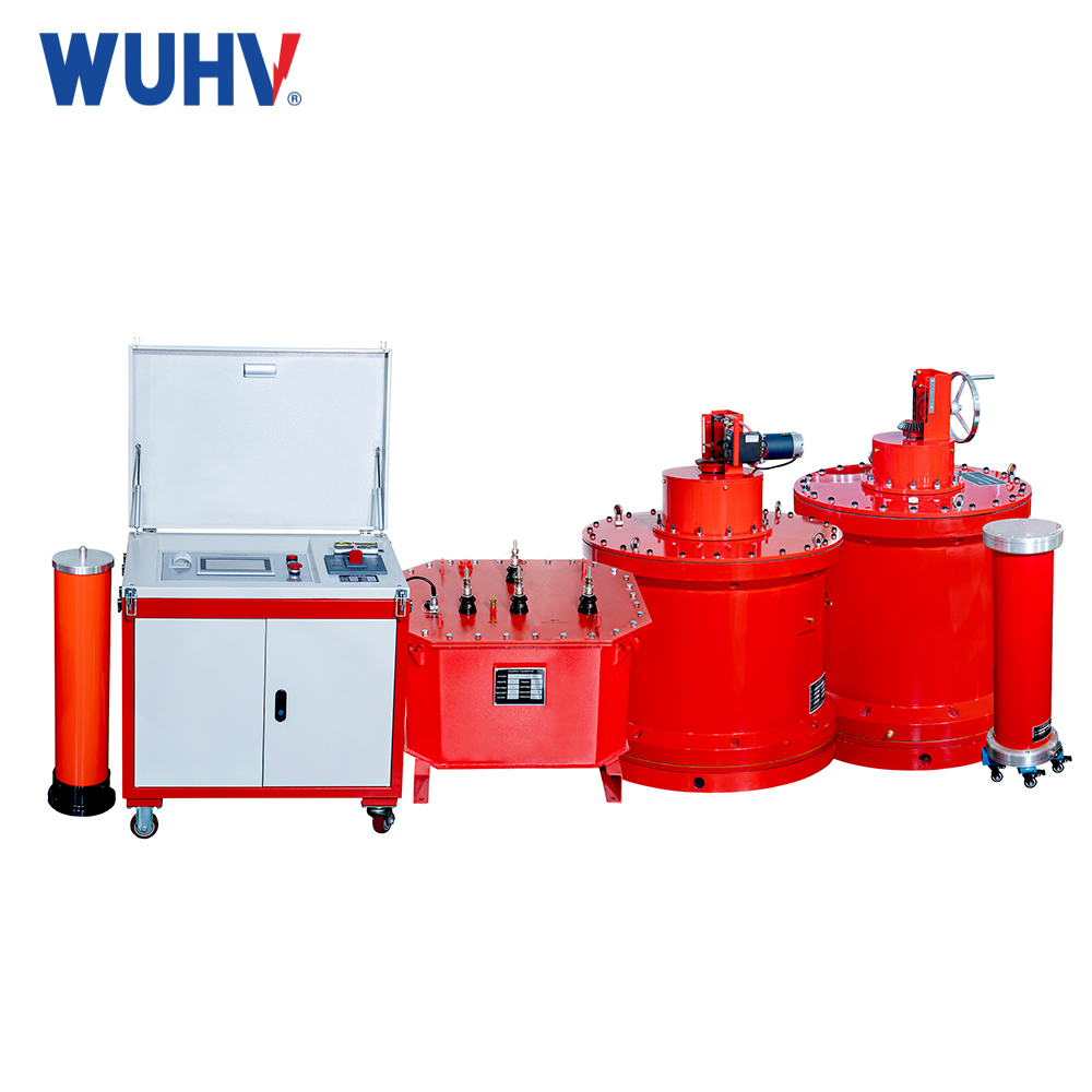
Today, as cross-linked polyethylene power cables become the mainstay of transmission and distribution networks, the periodic state assessment of cable insulation has become a core issue in power grid operation and maintenance. The 0.1Hz very-low frequency (VLF) withstand voltage test technology, with its advantages of effectively detecting insulation defects, small equipment size, and large capacity, has become the preferred solution for cross-linked cable testing recognized by the industry and written into relevant regulations.
However, when faced with very-low frequency high-voltage generators with different technological routes in the market, how to choose the equipment that truly matches the on-site needs? A core but often overlooked selection dimension is the instrument's ability to adapt to the load of large capacitance test samples. The power cable itself is a large capacitive load, and the equivalent capacitance of long-distance cables can reach several microfarads or even higher. If the capacitance driving capability of the instrument is insufficient, it will cause severe distortion of the output waveform or the inability to boost to the target value, resulting in test failure or misjudgment. Therefore, selecting a VLF withstand voltage tester based on cable capacitance is a crucial step in ensuring the effectiveness of the test.
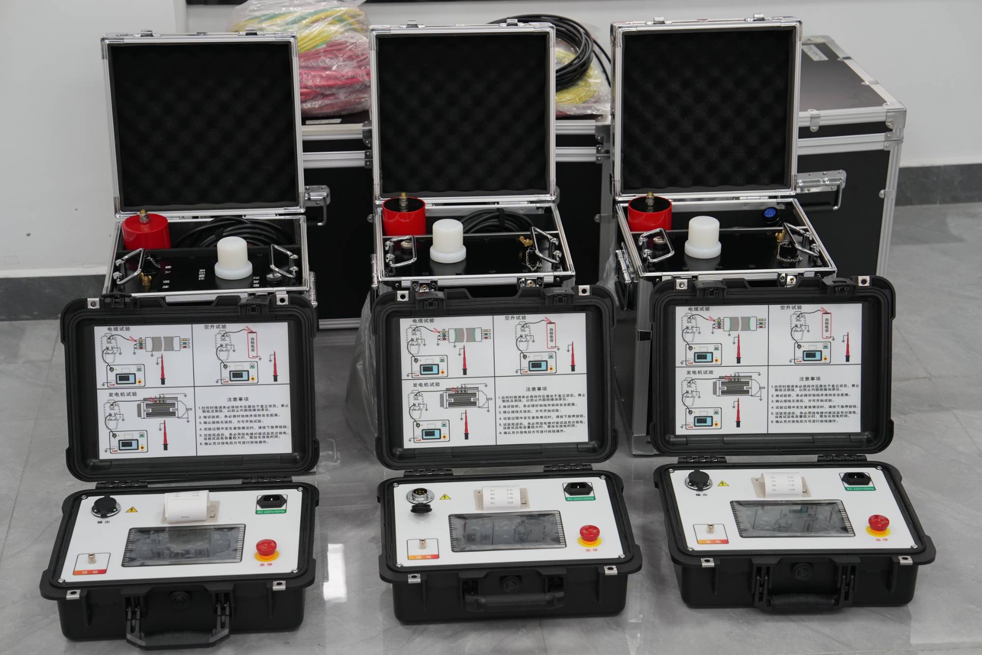
Cable capacitance: core parameter for VLF tester selection
のVLF voltage tester calibrates its carrying capacity based on the load capacitance (μ F). As a capacitive load, the capacitance of cables is directly related to factors such as cable length, cross-sectional area, and insulation material. The ultra-low frequency insulation withstand voltage test is actually an alternative method to the power frequency withstand voltage test - by reducing the frequency to 0.1Hz or even lower, the required power capacity is significantly reduced, resulting in a significant reduction in equipment volume and weight, theoretically with a capacity of about one fifth of the power frequency.
When selecting a VLF tester, it is necessary to ensure that the capacitance of the test sample is lower than the rated capacitance of the instrument. If the capacitance of the test sample is too small, the instrument will not be able to output normally; On the contrary, if the electrical capacity exceeds the rated value of the instrument, it may cause waveform distortion or inability to boost the voltage.
Selection steps based on cable capacitance
Step 1: Estimate the total electrical capacity of the tested cable
To choose a suitable VLF tester, it is first necessary to clarify the maximum cable length and corresponding capacitance that may be encountered in daily testing. The capacitance value per unit length of the cable can be obtained from the cable manufacturer or referred to relevant standards. Multiplying the unit length capacitance by the cable length yields the total electrical capacity.
Step 2: Match the rated capacitance and operating frequency of the instrument
VLF testers typically support multiple output frequencies such as 0.1Hz, 0.05Hz, 0.02Hz, and even 0.01Hz. The lower the output frequency, the larger the cable capacitance that can be driven.
Taking the Wuhan UHV VLF series products as an example, the same 30/1.1 model can carry 1.1 μ F at 0.1Hz, 2.2 μ F at 0.05Hz, 5.5 μ F at 0.02Hz, and 11 μ F at 0.01Hz. The 40/0.8 model can carry 0.8 μ F at 0.1Hz, 1.6 μ F at 0.05Hz, and 4 μ F at 0.02Hz.
Step 3: Balancing the Load Capacity at 0.1Hz
It should be noted that although reducing the frequency can improve the load-carrying capacity, cable diagnostic tests such as Tan Delta and Partial Discharge typically require testing at 0.1Hz. Therefore, if there are plans to conduct cable condition diagnostic testing in the future, priority should be given to selecting models with higher μ F ratings at 0.1Hz.
Step 4: Verify waveform quality and safety
In addition to capacitor matching, attention should also be paid to the output waveform quality of the instrument. The waveform quality of a standard sine wave output VLF high-voltage generator is directly related to the accurate application of the test voltage peak and the reliability of breakdown determination. Compared to some technical solutions that use high-voltage capacitor charging and discharging to generate approximate sine waves, pure sine wave output can more realistically simulate the voltage stress that cables bear under working conditions, and the test results have good equivalence with power frequency withstand voltage.
In terms of safety, the instrument should have multiple protection mechanisms such as output short-circuit protection, overvoltage protection, discharge protection, and automatic discharge function after the test is completed.
Choosing a VLF voltage tester is not just about looking at the voltage level. The core parameter of cable capacitance directly determines whether the instrument can operate normally under actual working conditions on site. When selecting, the maximum cable capacitance that may be encountered in daily testing should be estimated first, and then the model with sufficient rated capacitance coverage at the corresponding operating frequency should be selected based on this. At the same time, taking into account the load capacity at 0.1Hz to meet future diagnostic testing needs, and ensuring that waveform quality and safety protection mechanisms meet requirements. Only in this way can we select a VLF high-voltage generator that truly meets the on-site requirements and ensures the effectiveness of the test.