


Product Introduction
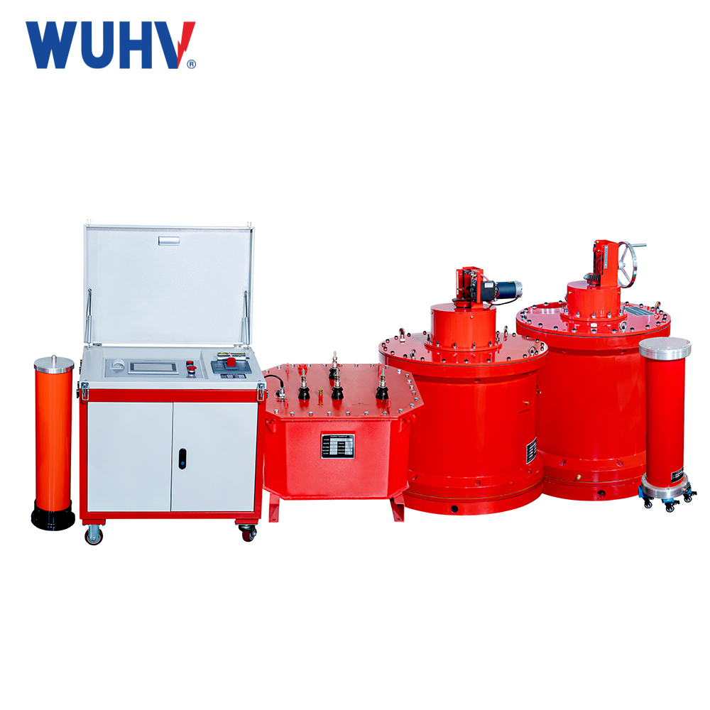
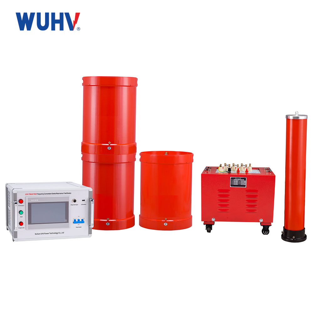
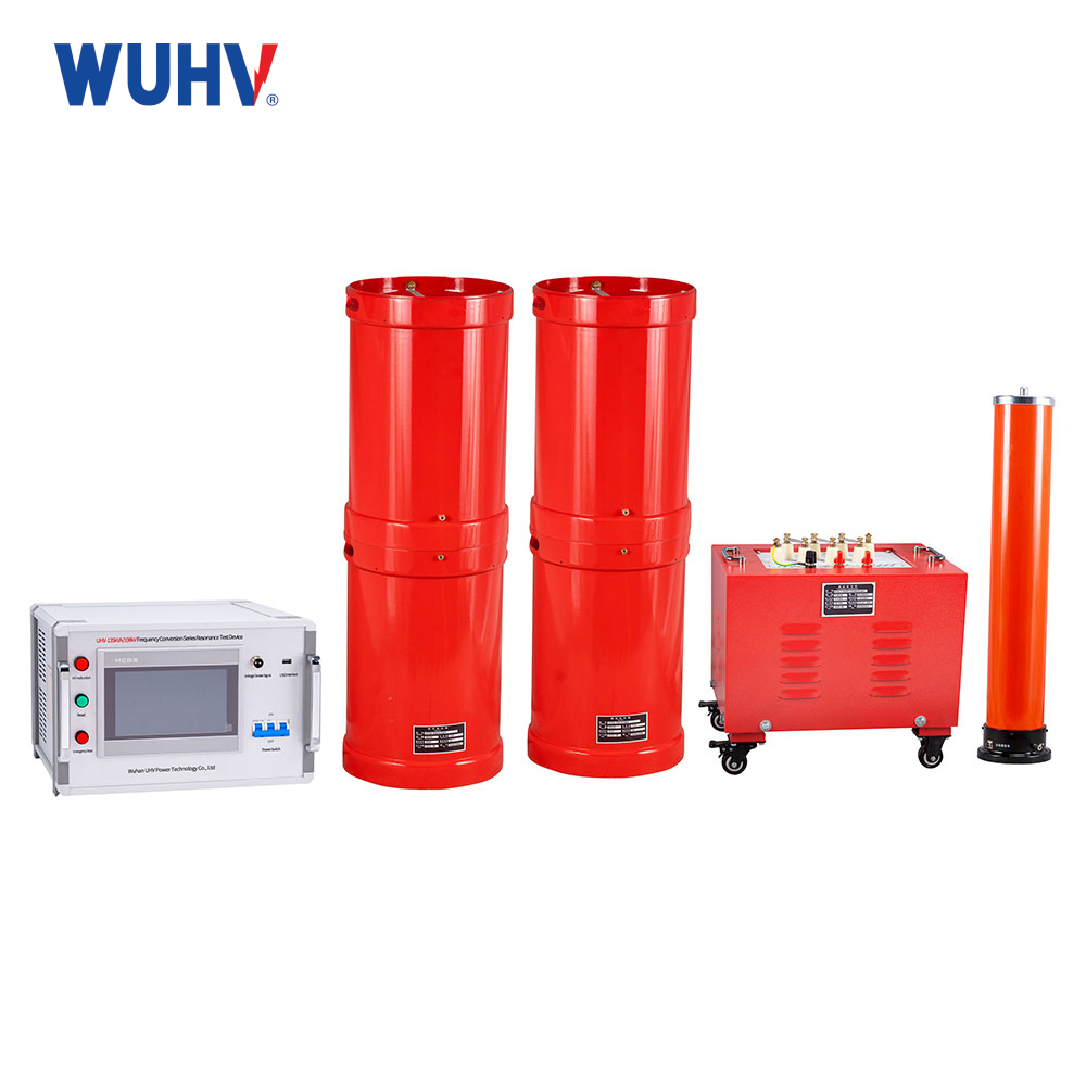
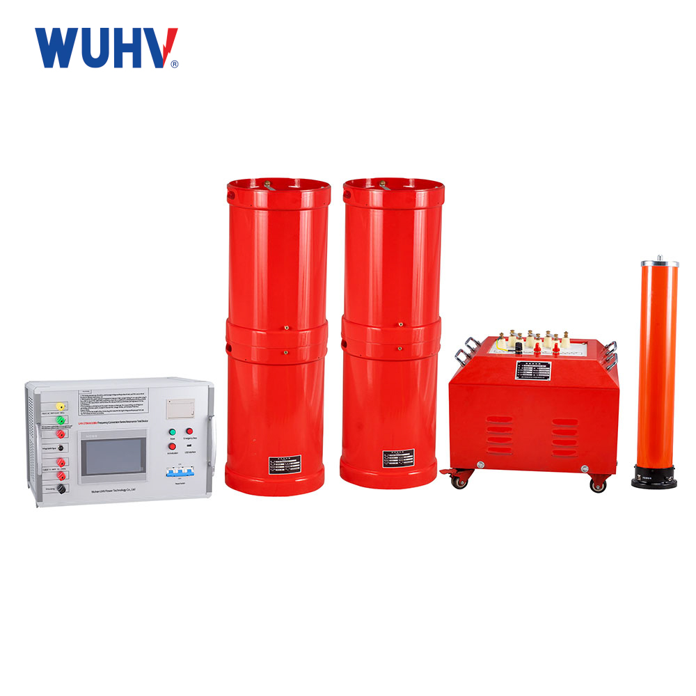
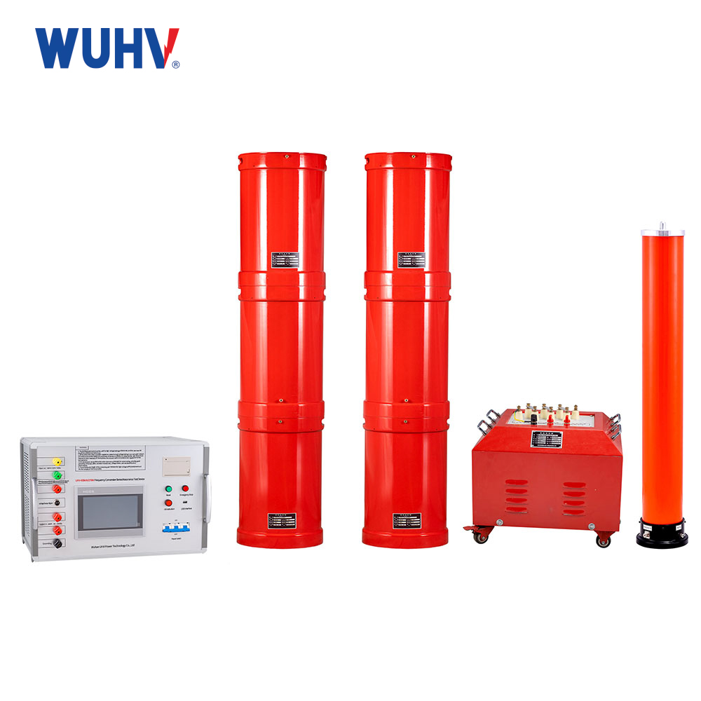
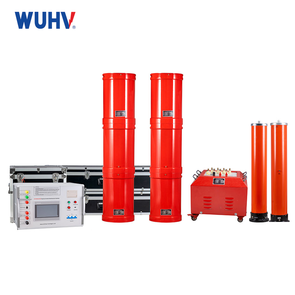
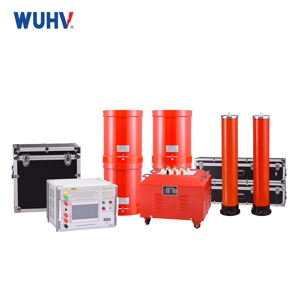
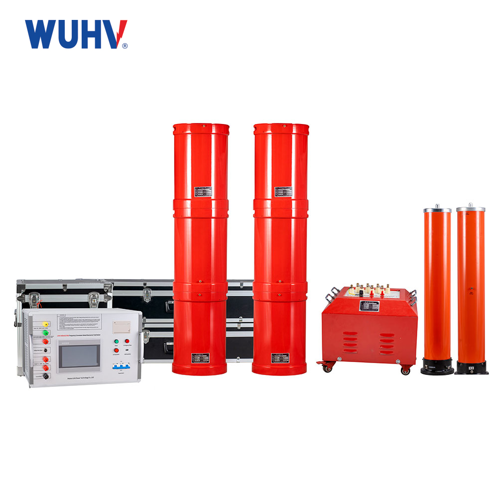
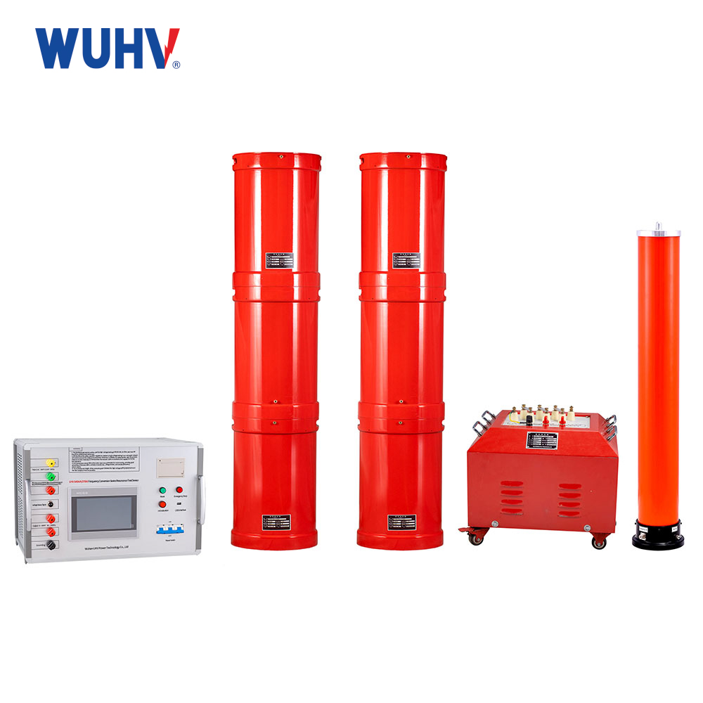
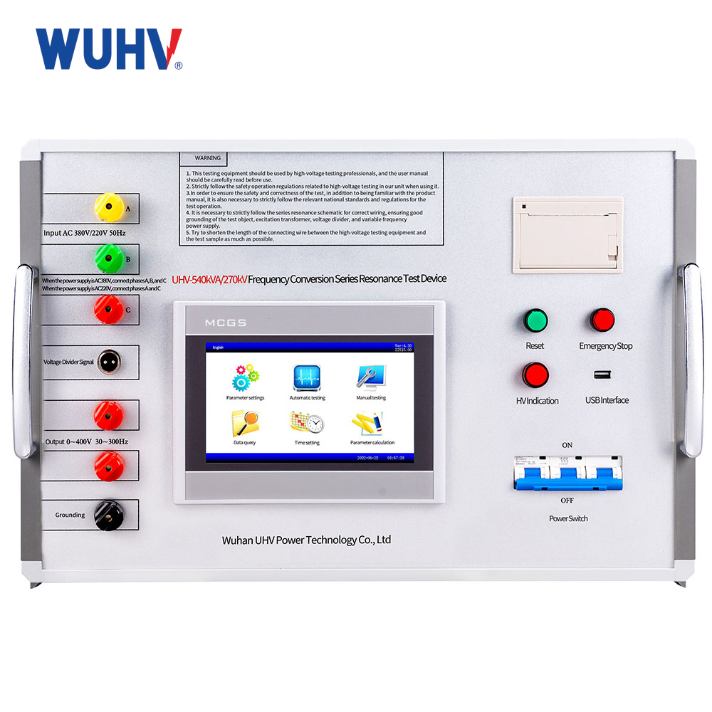
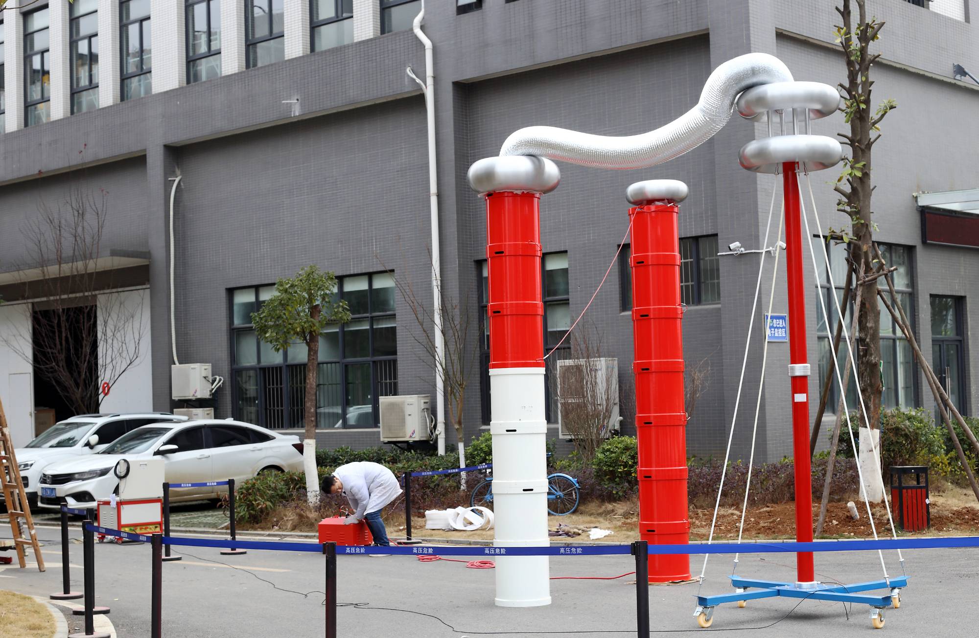
The high voltage 500kv GIS ac resonant test system manufactures is a high‑voltage test set that uses series resonance between an adjustable reactor and a capacitive test object (e.g. XLPE cable, GIS, transformer winding) to produce high AC test voltage with relatively low input power. By tuning the frequency so the inductive reactance of the reactor equals the capacitive reactance of the object, the circuit reaches resonance and the voltage across the test object is amplified according to the system’s Q‑factor.
Meet the test range
1, AC withstand voltage test for 10kV/300mm² cable 4.5km, capacitance ≤1.6897μF, test frequency 30-300Hz, test voltage 22kV, test duration 5 minutes.
2, AC withstand voltage test for 35kV/300mm² cable 1.8km, capacitance ≤0.3501μF, test frequency 30-300Hz, test voltage 52kV, test duration 60 minutes.
3, AC withstand voltage test for 35kV voltage level switchgear, test frequency 30-300Hz, test voltage not exceeding 95kV, test duration 1 minute.
4, AC withstand voltage test for 110kV/300mm² cable 1km, capacitance ≤0.147μF, test frequency 30-300Hz, test voltage 128kV, test duration 60 minutes.
5, Full insulation AC withstand voltage test for 110kV/50MVA main transformer, capacitance ≤0.02μF, test frequency 45-65Hz, test voltage not exceeding 160kV, test duration 1 minute.
6, AC withstand voltage test for 110kV voltage level switch and other electrical equipment, test frequency 30-300Hz, test voltage not exceeding 265kV, test duration 1 minute.
 |  |
Main components of the device
| Serial number | 装置名 | Specification and model | ユニット | Quantity |
| 1 | Variable frequency power supply | UHV-30kW | Tower | 1 |
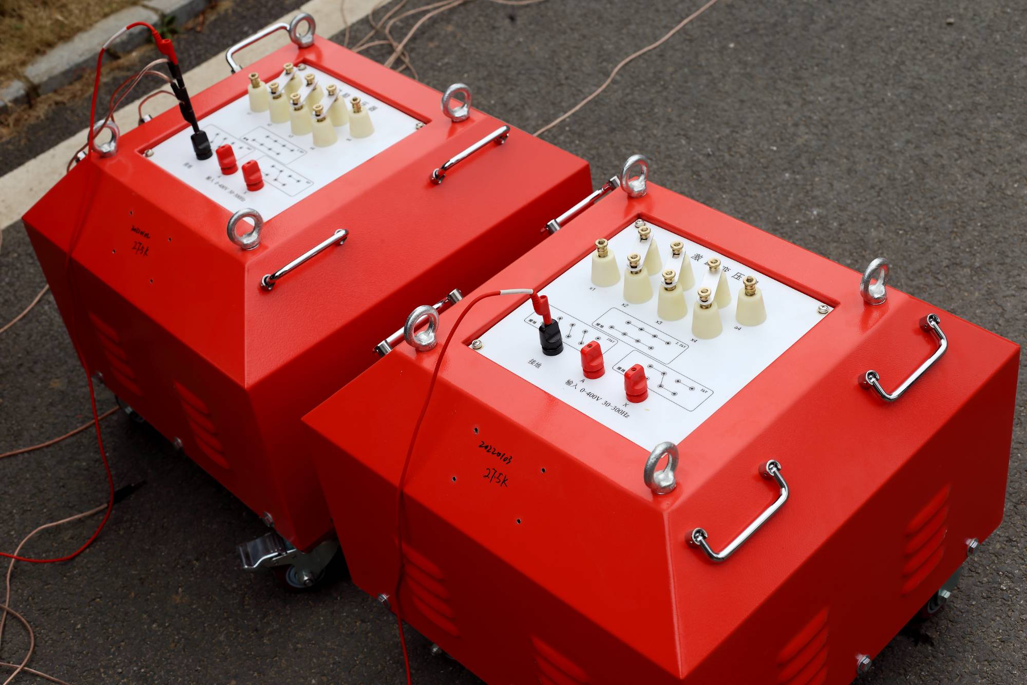
| 2 | 励磁トランス | UHV-30kVA/1.5/3/6kV/0.4kV | Tower | 1 |
| HTJL-15kVA/16kV | Tower | 1 | ||
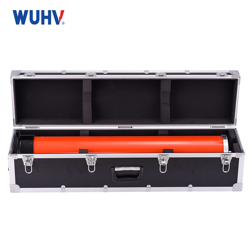
| 3 | High voltage reactor | UHV-54kVA/27kV | Tower | 10 |
| 4 | Capacitive voltage divider | UHV-500pF/270kV | セット | 1 |
Main technical parameters and functions
| 定格出力 | 540kVA |
| 定格電圧 | 54kV;135kV;270kV |
| 定格電流 | 10A;4A;2A |
| 測定精度 | System RMS level 1.5 |
| Operating frequency | 30-300Hz |
| Device output waveform | Sinusoidal wave |
| 品質係数 | Device Q≥30(f=45Hz) |
| 波形歪み率 | Output voltage waveform distortion ≤1% |
| 入力電源 | Single-phase 220 or three-phase 380V voltage, frequency 50Hz |
| Working hours | Allow continuous 60min under rated load; Overpressure 1.1 times 1 minute |
| 温度上昇 | Temperature rise ≤65K after continuous operation under rated load for 60 minutes |
| Protection function | Overvoltage, overcurrent, zero start, system mismatch (flashover) and other protection functions |
| 周囲温度 | -20℃-55℃ |
| 相対湿度 | ≤90%RH |
| 高度 | ≤3000m |
Main Features
1. Significant reduction in power capacity and equipment lightweighting: By using a series resonance between the reactor and the test capacitor, the power supply only needs to provide the loss of active power in the circuit, so the required input capacity is ten times smaller than that of the test transformer, making the entire equipment small in size and light in weight, especially suitable for on-site handling and use.
2. Good output voltage waveform: In resonance state, the output is a perfect power frequency sine wave, fully complying with the waveform requirements of the national standard for withstand voltage testing, and the test assessment is accurate and effective.
3. Excellent safety guarantee performance: When the test sample flashover or breakdown occurs, the resonance condition is immediately destroyed, the high-voltage output automatically drops sharply, and the fault current is greatly reduced, thereby forming a natural "soft protection" for the test sample and the device itself, greatly reducing the risk of destruction.
4. Strong adaptability and wide application: By adjusting the inductance (or power frequency) of the reactor, the high voltage series resonant test set for 500kv GIS factory can adapt to different capacitance samples and easily achieve resonance state, especially suitable for testing long cables and GIS with huge capacitance.
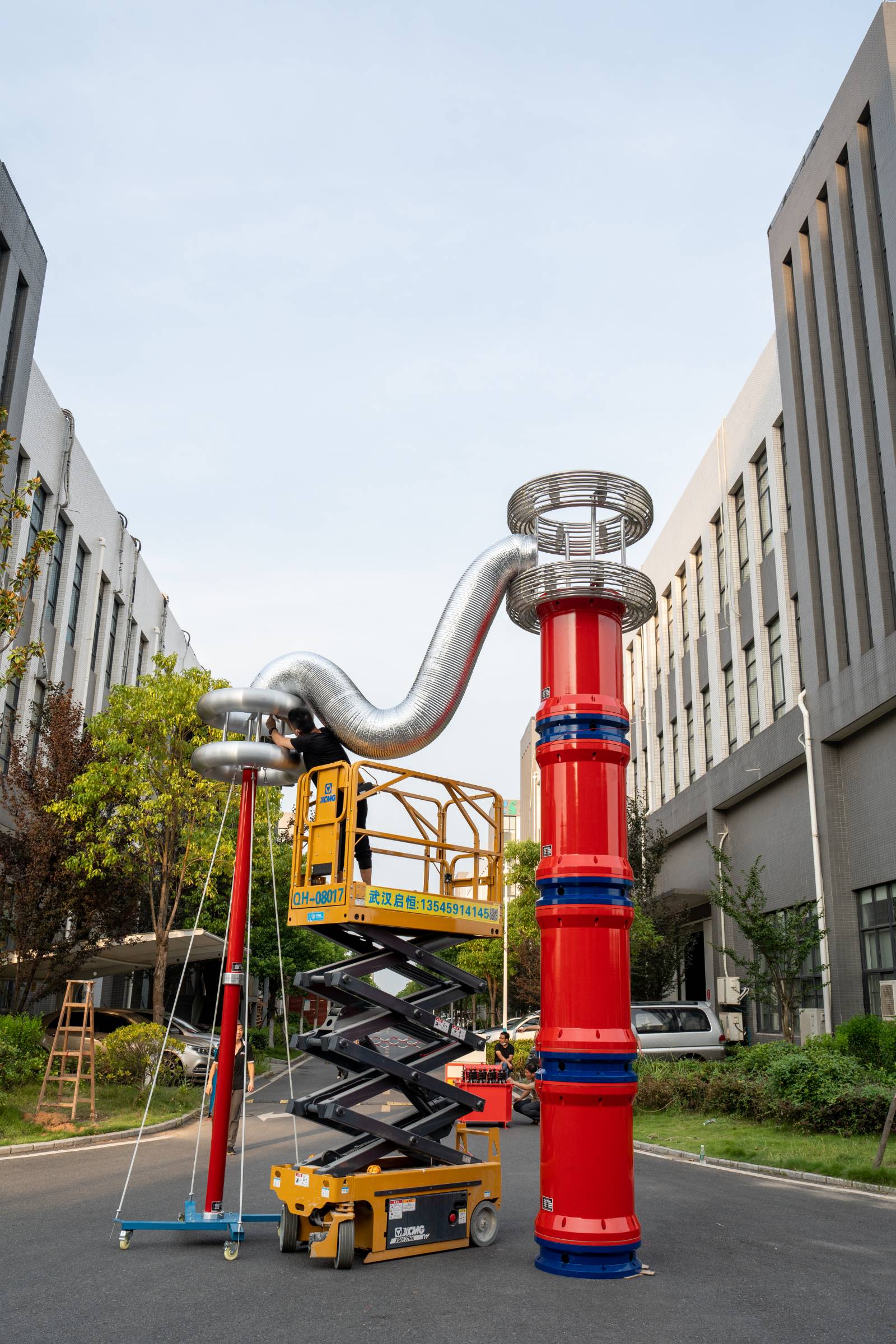 |
|
|
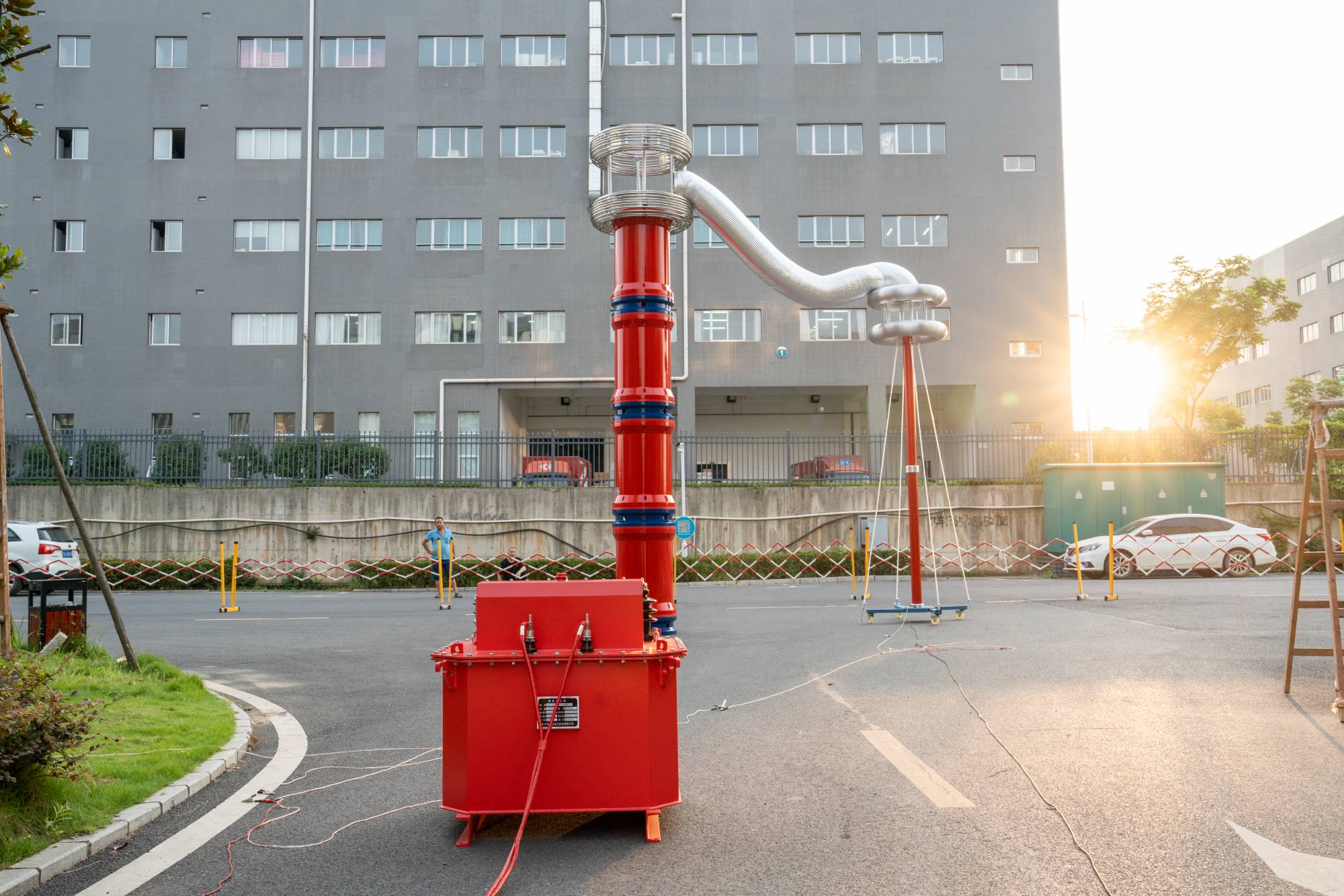
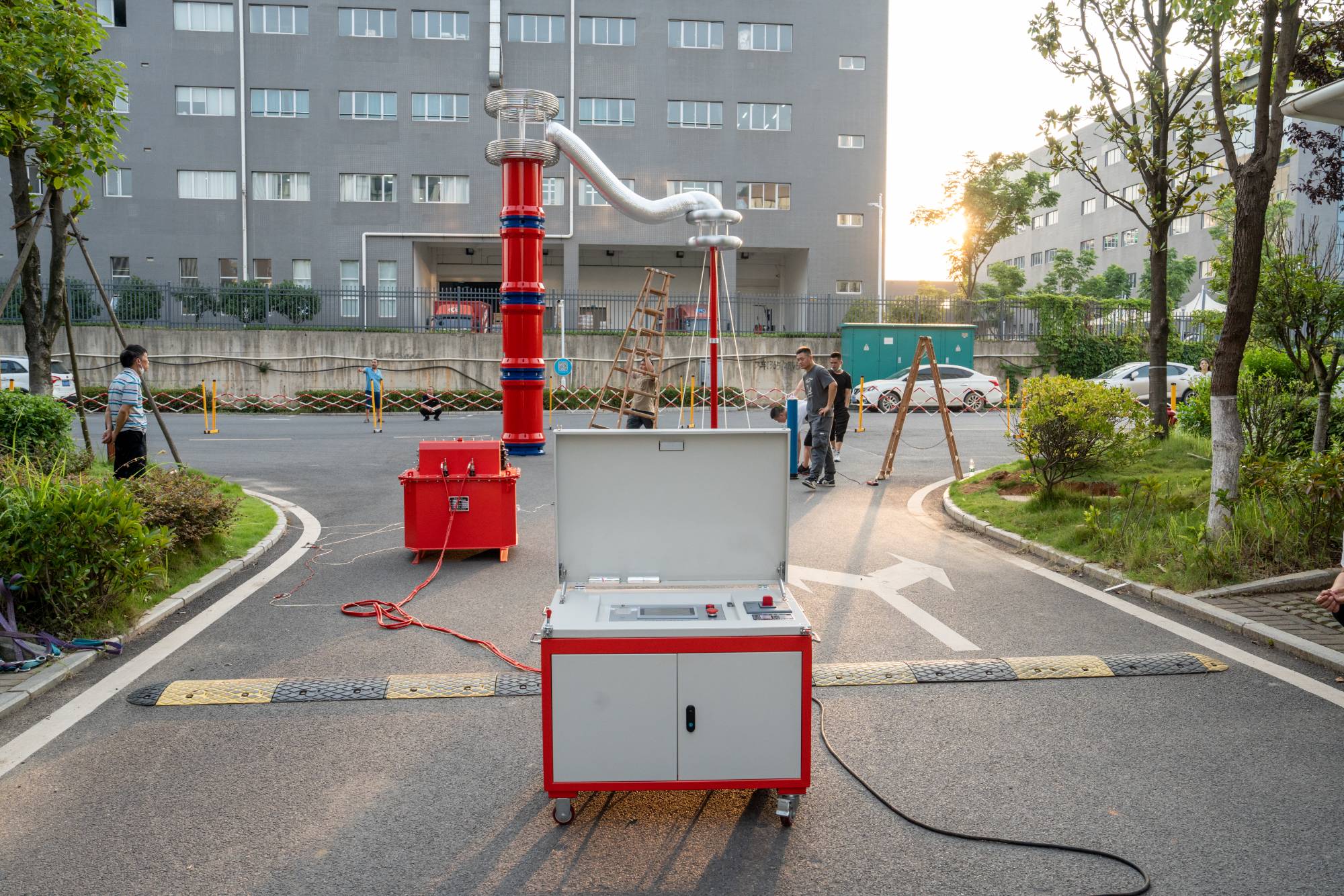
FAQ
Q: What is the difference between a series resonant system and a conventional power-frequency test transformer?
A: A conventional transformer boosts voltage directly and requires a large power supply capacity. In contrast, series resonant test system manufactures uses reactors (inductors) to compensate for the capacitive reactance of the test object. The required power supply capacity is only 1/Q of that of traditional equipment (where Q is the quality factor). This makes the system much lighter and portable, ideal for on‑site mobile testing.
Q: How do I determine if the number of reactors configured is sufficient?
A: The resonance condition f = 1 / (2π√LC) must be satisfied. Calculate the resonant frequency based on the test object capacitance (C) and reactor inductance (L), and ensure that the frequency falls within the adjustable range of the system (typically 20–300 Hz). If the frequency is too high, connect more reactors in parallel to increase inductance; if too low, change the connection (series/parallel combination) to reduce total inductance.
Q: Why is reliable grounding mandatory for on‑site testing?
A: For two reasons:
① to ensure accurate measurement by the high‑voltage divider, avoiding ground potential rise interference;
② to provide a safe discharge path for fault currents in case of breakdown or abnormal discharge, protecting both equipment and personnel.
Q: In which cases is a series resonant system not suitable?
A: It is not suitable for purely resistive loads (e.g., dry‑type transformer windings) or very small capacitive loads (e.g., short cables), because resonance test device supplier is difficult to achieve or the resonant frequency would be too high, exceeding the system’s range. In such cases, a power‑frequency test transformer should be used instead.