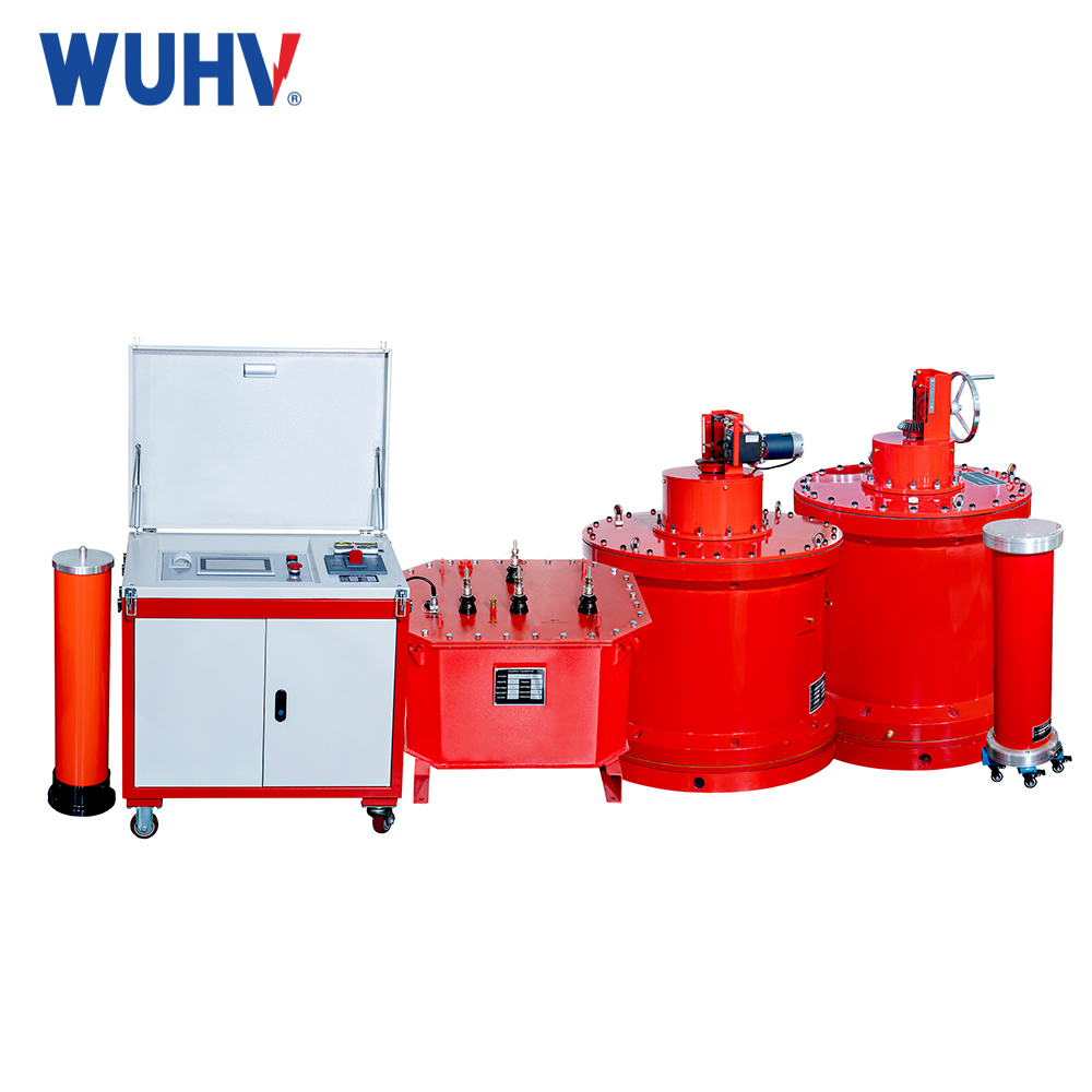
The principle of frequency conversion series resonance? Wuhan UHV specializes in the production of 直列共振, with a wide range of product selection and professional electrical testing. To find 直列共振, choose Wuhan UHV.
1、 Principle of Frequency Conversion Series Resonance
Analysis of the principle of variable frequency series resonance: In a series circuit composed of resistors, inductors, and capacitors, when the capacitance and inductance are equal, the voltage and current phases in the circuit are the same, and the circuit exhibits pure resistance, which is called series resonance. When a series resonance occurs in a circuit, the impedance of the circuit is Z=R, at which point the total impedance of the circuit is minimized and the current of the circuit is maximized. The diagram shows a one port network composed of inductor and capacitor elements in series. Its equivalent impedance is such that when resonance occurs, the port voltage and current are in phase. Therefore, the resonant angular frequency and resonant frequency can be derived as. The inductive or capacitive impedance at resonance is defined as the characteristic impedance ρ, and the ratio of the characteristic impedance ρ to the resistance R is the quality factor Q
When the circuit resonates, the impedance value is minimized. When the port voltage is constant, the circuit current will reach its maximum value, as shown, and the magnitude of this value is only related to the resistance value of the resistor and not to the inductance and capacitance. During resonance, the inductance voltage and capacitance voltage are equal in value and opposite in phase, which is Q times the total voltage [4]. The current of an RLC series circuit is a function of the power supply frequency, that is, under the condition that the inductance L, capacitance C, and power supply voltage US of the circuit remain unchanged, different R values result in different Q values. The current amplitude frequency characteristic curve at different Q values is shown.
In order to study the influence of circuit parameters on resonance characteristics, a general resonance curve is usually used, as shown in the general resonance curve of a series resonant circuit. The shape of the universal resonance curve is only related to the Q value, and the sharper the curve shape, the better the frequency selection performance of the circuit. The frequency range corresponding to an amplitude greater than 0.707 times the peak value is the passband. Theoretical derivation shows that the passband is inversely proportional to the quality factor.
2、 Application of frequency conversion series resonance
When analyzing the application of variable frequency series resonance, the resonant frequency of variable frequency series resonance, where L is the inductance value of the reactor, should be considered for the influence of mutual inductance if several reactors are used in series or parallel; C is the sum of the test sample and the voltage divider capacitor, which can be measured on-site using an electric bridge or dielectric loss meter. High voltage current I=2 π fCU, the on-site withstand voltage test voltage U can be determined by the electrical parameters of the test sample and the factory withstand voltage test value; active power P=1.2 (P0+PK), where P0 is the no-load loss of the excitation transformer and PK is the rated active loss of the reactor.
During the frequency conversion series resonance test, the capacity of the excitation transformer should be greater than the active power P, and the transformation ratio of the excitation transformer should be reduced as much as possible on the premise that the minimum output voltage of the excitation transformer meets the test requirements, so as to correspondingly reduce the input current on the primary side of the excitation transformer. The capacity of the experimental power supply is S=P+P1, where P1 is the loss of the variable frequency power supply itself. The power supply current I1 can be obtained by inputting a voltage of 380V from the power supply terminal. The rated voltage and current of the reactor in the experiment should also be greater than the test voltage and high voltage current. When the reactor is connected in series or parallel to meet the test requirements, the voltage and current borne by each reactor must be calculated to not exceed the limit.
In field tests, bare copper wire with a diameter of 16mm2 or more is usually used for grounding. The parasitic inductance of bare copper wire is in the order of μ H, about 0.1-1 μ H/m, and the DC resistance is about 0.1m Ω. If the grounding wire is bent and surrounded, the inductance can be increased to 10-1000 μ H/m. The insulation of the test sample is usually broken down at the positive or negative peak of the AC voltage. The voltage on the test sample is highest at the moment of breakdown, and the time for the voltage on the test sample to drop to zero after breakdown is generally between 0.1-10 μ s, depending on the actual situation of the breakdown point. From the perspective of discharge energy, even during discharge, the minimum capacitance of the test sample is only 0.002 μ F, but in actual testing, the capacitance of the test sample is much larger than this value. If the discharge frequency is 100kHz, the parasitic inductance of the ground wire is 1 μ H, and the discharge current is 1000A, the parasitic inductance of the ground wire XL==0.628 Ω, and the overvoltage Ud=If XL=1000 × 0.628=628V that may be generated by the ground wire. If the ground wire connection is not standardized, the parasitic inductance will increase significantly, and the generated overvoltage may be even greater, which can endanger the variable frequency power supply and personal safety. Therefore, the high-voltage testing system must have a reliable grounding point. The grounding point of the voltage divider should be connected to the ground as short as possible, and the grounding wire should be thick, straight, and short to ensure the safety of the test.


